The Sugarhouse Streetcar Project
- Date: 8/15/2014
- Project Type: Construction Phases
The Sugarhouse Streetcar Project
About this Project
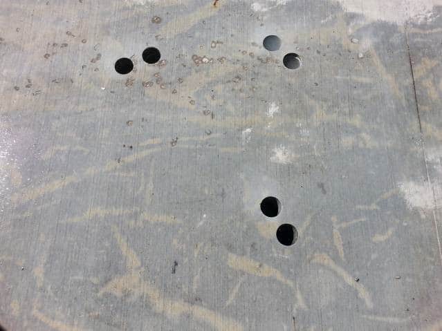
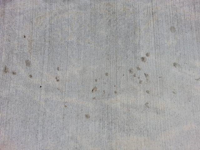
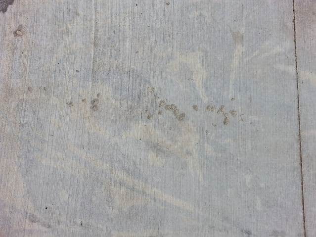
Concrete placed about 9 to 12 months ago for the Sugarhouse Streetcar Project in Salt Lake City, Utah has sustained sporadic surface defects most of them exposing aggregates in the concrete. Stakeholders in the project are interested in finding the cause. The causes of the defects are to be evaluated using ASTM method C856 “Petrographic Examination of Hardened Concrete”
Note – This featured project report is an abreviated version of the actual report prepared for the client.

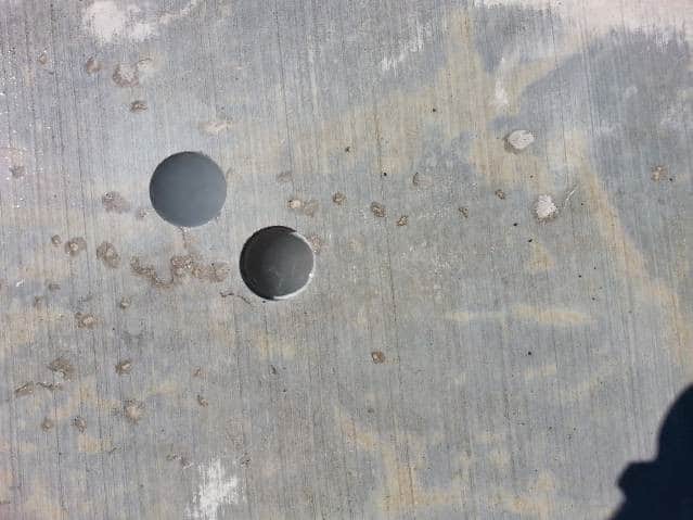
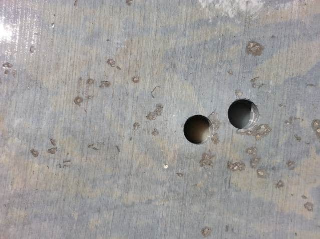
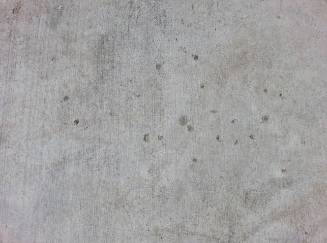
Representative sections of surface defects
Samples
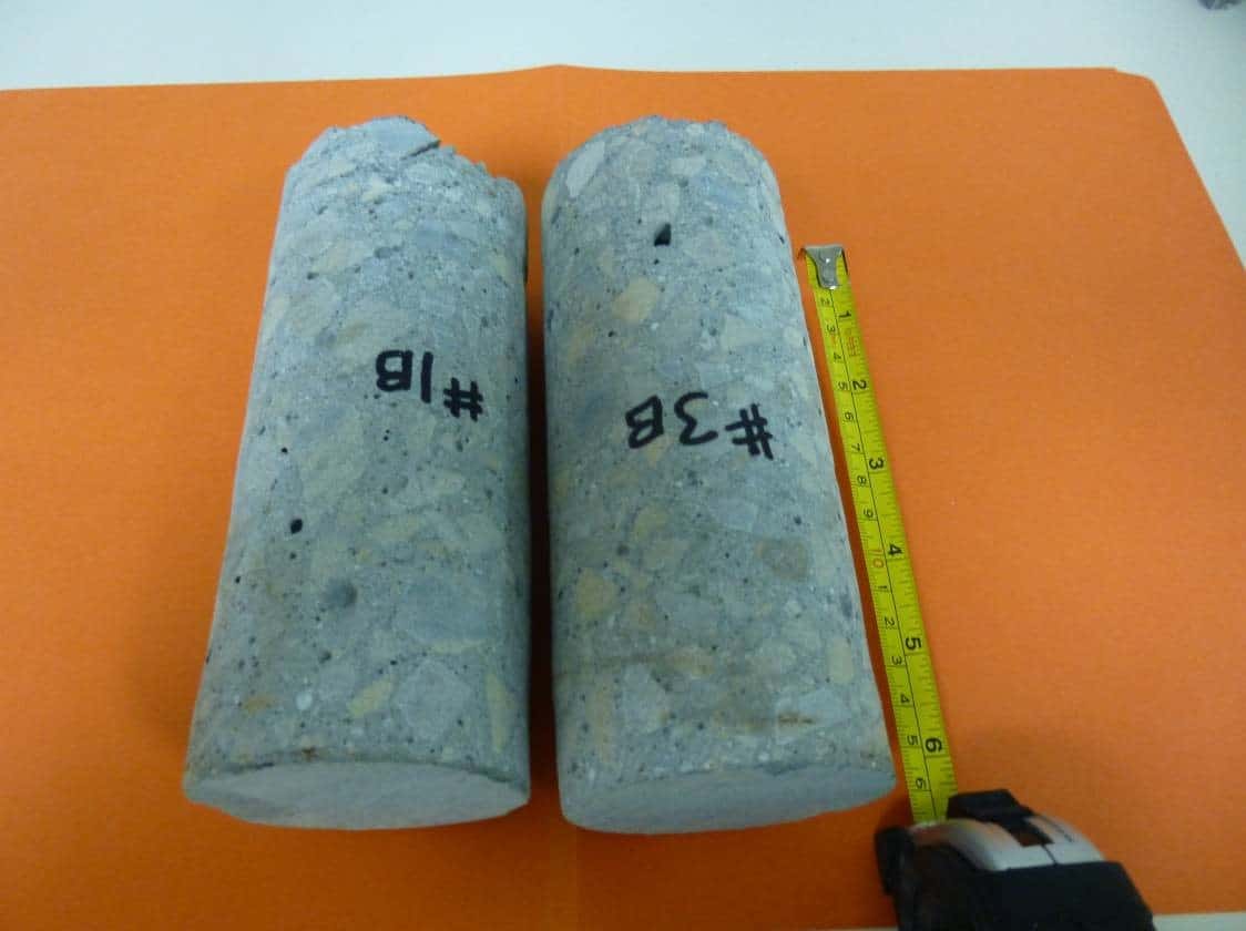
Two cored samples, approximately 2-3/4” in diameter and about 6-1/2” long, were submitted to our laboratory for the evaluation. Both surfaces were smooth with a scratched defect on each surface. The cores show aggregate at the bottom of core which is indicative of the cores being full-depth, i.e. the thickness of slab is about 6”. The coarse aggregate is quartzite with a maximum size of 1” and is well distributed in the core. Honeycombs show on the sides of both cores.
Below – honeycombs and visible voids of sizes smaller than the honeycombs that are fairly well distributed along the entire lengths of both cores.
Test
Petrographic Examination of Hardened Concrete, ASTM C 856
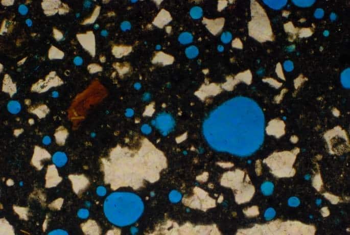
Petrographic analysis involves the optical examination of concrete specimen under low and high power magnification. Detailed instructions on conducting a petrographic examination of hardened concrete/mortar can be found in ASTM C856, “Standard Practice for Petrographic Examination of Hardened Concrete”. For our examination, a section of the sample was taken and impregnated with blue dye under vacuum. The impregnation under vacuum causes the dye to permeate every crack, micro crack and all pores, including micro pores in the concrete sample. The impregnated concrete is cut and placed on a glass plate, ground and polished to a thickness of about 30 microns.
The sample was observed by polarizing microscope using a magnification of 40X.
The thin section of concrete was examined for the following features:
- Degree of hydration
- Approximate water-cement ratio
- Composition of fine aggregate
- Air content
- Presence of cracks and micro cracks
- Presence of deleterious reaction products
- Presence of mineral admixtures.
Purpose of Petrographic Examination
The usefulness of petrographic analysis ranges from quality control to predicting future performance of concrete; others include:
- Determination as to whether the concrete/mortar in a construction was or was not as specified.
- Determination as to whether the concrete has been subjected to and affected by sulfate attack, or other chemical attack, or early freezing, or to other harmful effects of freezing and thawing.
- Part of a survey of the safety of a structure for a present or proposed use.
Findings from Petrographic Analysis
Examination of sample revealed the following:
- The cement paste in the samples appears to be well hydrated; the paste section of concrete is uniform when viewed under the microscope. Unhydrated cement particles were noted in the microscopic examination but do not show in the photos taken. It must be pointed out, however, that unhydrated cement particles can even be seen in concretes 5 years or older.
- Cement content used in formulating the slab is estimated at 5½ ± ½ sack per cubic yard.
- The approximate water-to-cement ratio is in the range of 0.46 to 0.48.
- Coarse aggregate used is predominantly quartzite, some of which are porous and others have cracks in them. Maximum size of coarse aggregate is 1”. Fine aggregate is predominantly manufactured sand. The sand particle sizes are identified under the microscope to be mostly quartzite. The aggregates appear to be well bonded to dense cement paste.
- Both samples have entrained air and entrapped air, with a combined total ranging from about 12% to 14%. The entrained air content is estimated to be 8 – 9%; the entrapped air is about 4 – 5%. Included with the entrapped air are additional voids resulting from some chipped off sections of the coarse aggregate. These voids are formed during the latter period of the mixing of concrete at which point the mortar has thickened to the point where it cannot flow to fill the voids. The large entrapped voids may be formed from single or two or more aggregates in close proximity. Furthermore, such voids sometimes incorporate other entrapped air voids to create even bigger voids.
- No cracks were found in the paste section of the concrete; cracks and pores were noted in some of the coarse aggregate. Aggregate for concrete are supposed to be devoid of deposits, hard and strong.
- No deleterious reaction product was found in any of the two samples.
- Fly ash appears to have been in used in the formulation of the concrete.
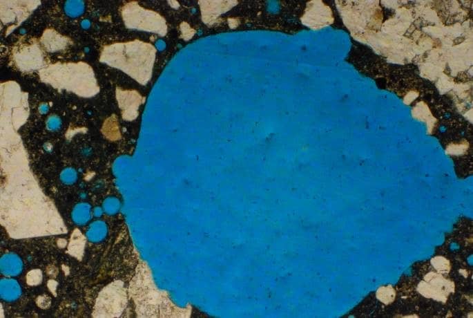
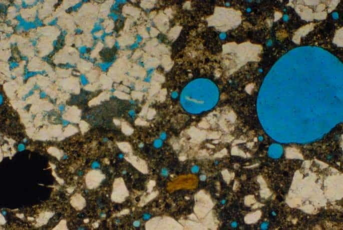
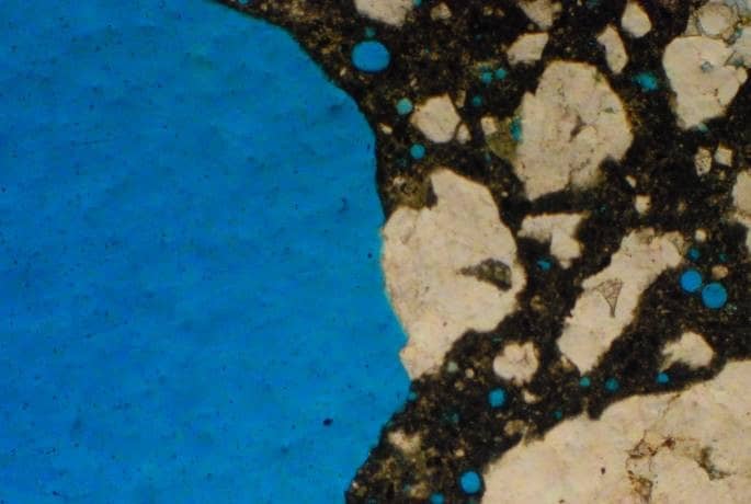
Photomicrographs from the petrographic analysis are shown
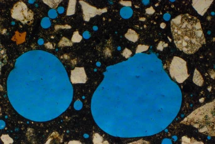
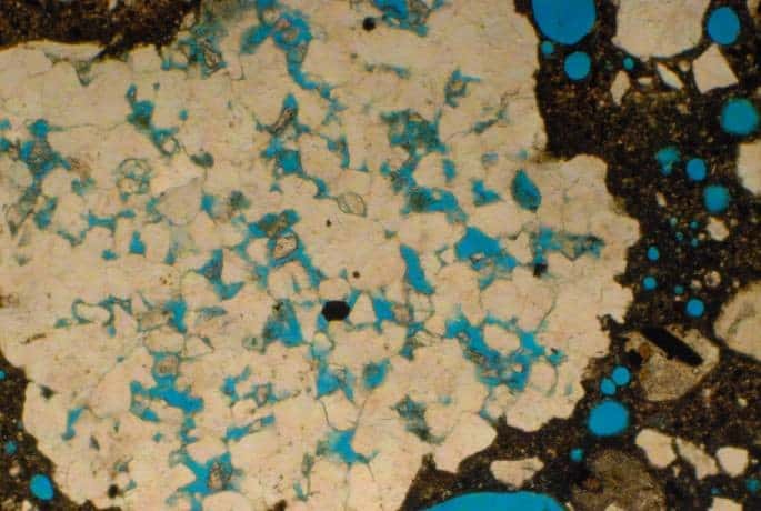
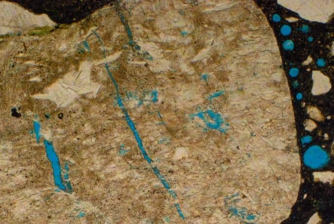
Figure 6 shows representative sections of Sample 1B.
Small-sized voids (blue round circles) fitting the size of entrained air voids are shown in Figures 6 a, b, c & d.
Larger-sized voids fitting the size of entrapped air are shown in Figure 6 b (yellow arrow)
Pores and cracks in aggregate are shown in Figure 6 c & d respectively.
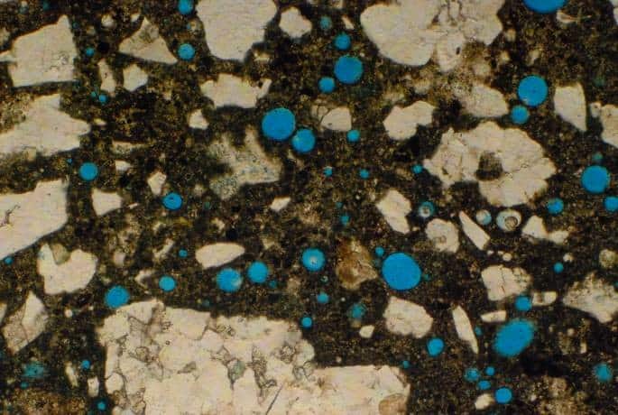
Entrained air void sized shown in Figures 7a, b, c & d.
Entrapped air sized voids (red arrow) is shown in Figure 7c.
Large air voids resulting from chipped off sections of coarse aggregate are seen in Figures 7b & d
Porous aggregate is shown in Figure 7c. (Yellow arrow)
DISCUSSION OF RESULTS
The noted defects are likely to be a combination of two factors, and they are:
- High entrapped air content/honeycombs, estimated at 4-5%. This includes voids from chipped off sections of coarse aggregate (see Figure 7 b & d), and
- Porous and cracked aggregate. Aggregate used in concrete is expected to be devoid of deposits, hard and strong. The aggregate used in the concrete was found to be porous and/or cracked. The cracks contributed to the entrapped air voids of varying sizes in the concrete.
The estimated entrained air content of 8 – 9% is sufficient to resist frost (freeze-thaw); for concrete with 1” maximum size coarse aggregate about 6% entrained air is recommended in severe exposure environment [2]. Entrained air void sizes are typically in the range of 10 µm to 100 µm (0.1mm) in diameter.
Entrapped air voids are 1000 µm (1mm) or larger in size and are estimated to be 1 – 2% in a well compacted concrete [3]. Kosmatska [4] attributes entrapped air voids to be a function of aggregate characteristics for a 1” maximum-size aggregate in a non-air-entrained concrete the estimated entrapped air is about 1.5%
[3] Composition and Properties of Concrete, Troxell G.E., Davis H.E. and Kelly J.E., McGraw-Hill Book Company, Second Edition, 1968
[4] Design and Control of Concrete Mixtures, Kosmatka S.H and Wilson, M.L. Portland Cement Association Engineering Bulletin 001, 15th Edition, 2012
Consulting Engineers
Concrete Experts
"C3S, Inc. is a concrete consulting firm dedicated to providing full scale services to civil, A/E firms, government entities, testing laboratories, property managers and owners, and other agencies dealing with projects related to concrete.
With its immense expertise, C3S. Inc. has been successfully serving clients in U.S and worldwide markets for over 30 years. "
CONTACT INFORMATION
C3S, Inc.
7100 Regency Square Blvd.
Suite 183
Houston, TX 77036
Office Hours
Mon-Fri: 8 AM - 5 PM
Sat-Sun: Closed

