The Crown Castle Tower Project
- Date: 02 May, 2012
- Project Type: Maintenance/Forensic Phase
The Crown Castle Tower Project
About this Project
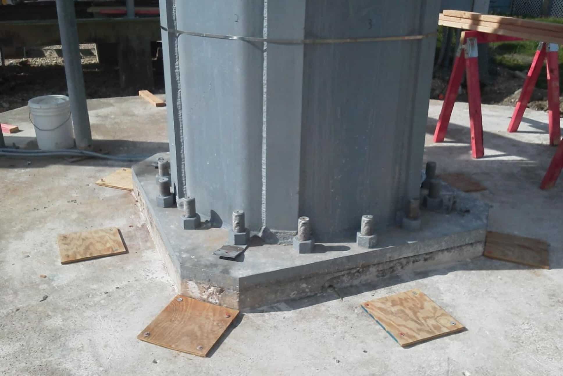
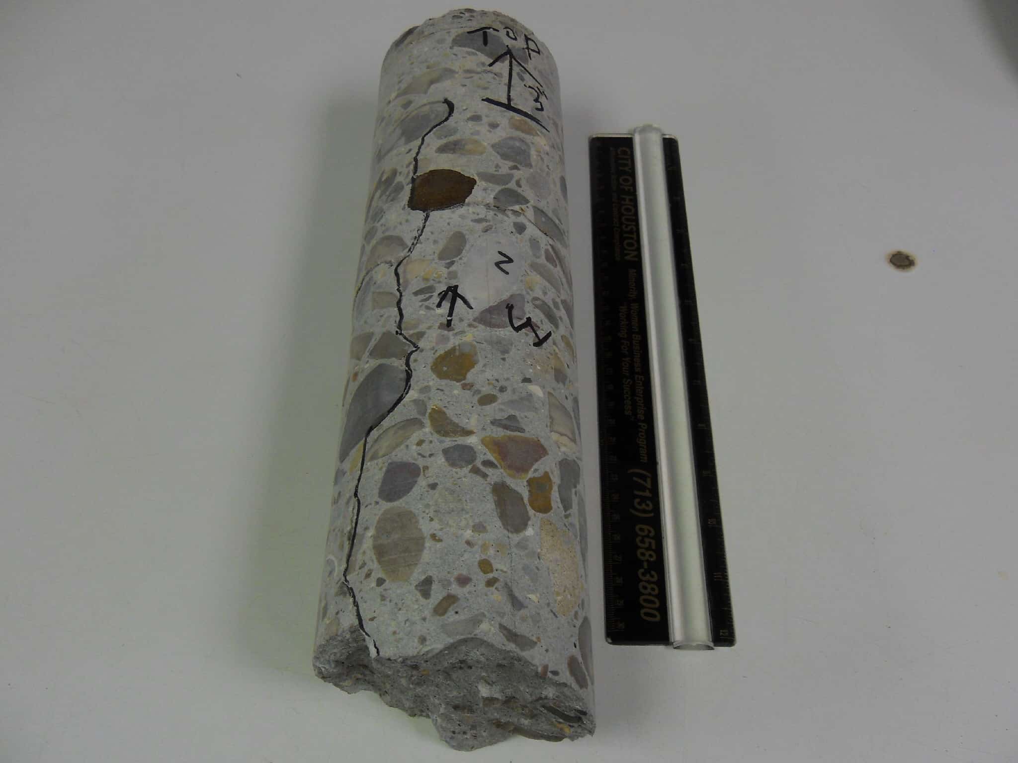
Concrete at the base of a communication tower, upon coring, was found to have vertical cracks in the samples. The concrete is said to have been placed over 15 years ago. Owner of tower is desirous in finding the cause of this defect in the structure.
Two concrete cores were inspected at the offices of the client. One of the cores was selected for evaluation by petrographic analysis.
The concrete appear to have been formulated with acceptable ingredients in the right proportions. There are differentially set mortar sections in the concrete that provided avenues for stresses applied on the concrete to be relieved by propagating as cracks in the concrete. One of the most probable causes of differential setting of mortar in concrete is re-tempering. Re-tempering is the addition of water to a hardening fresh concrete and re-mixing it for a while to render it easy to pour and place.
Note – This featured project report is an abbreviated version of the actual report prepared for the client.
Samples
A 3-1/2” diameter core and about 16” long was picked from two similar samples for evaluation. The bottom of both samples was broken off. The samples have a typical gray concrete coloration and appeared to have fairly well distributed aggregates across the entire cores. Both of them had vertical cracks along the cores.
Test
Petrographic Examination of Hardened Concrete, ASTM C 856
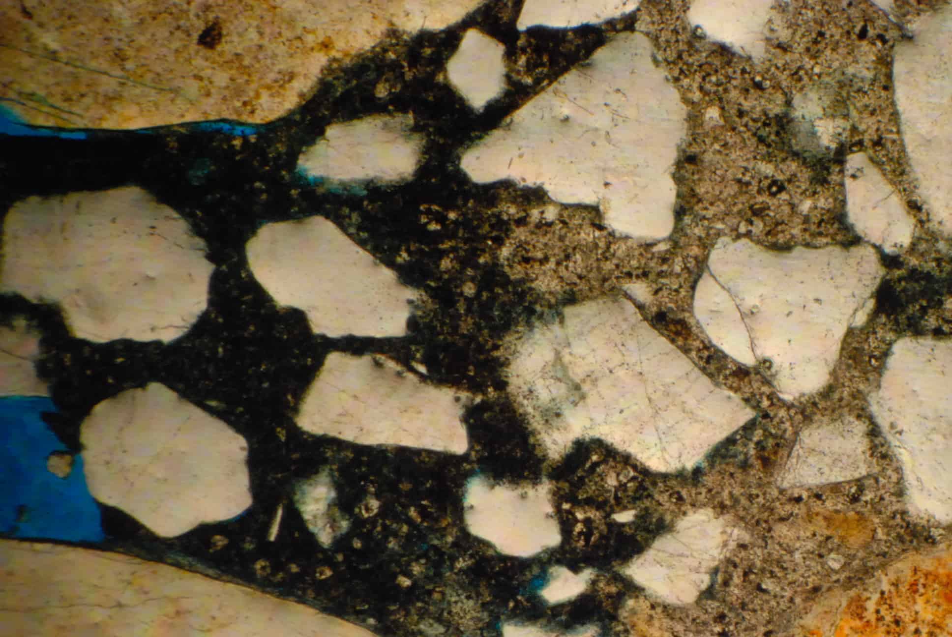
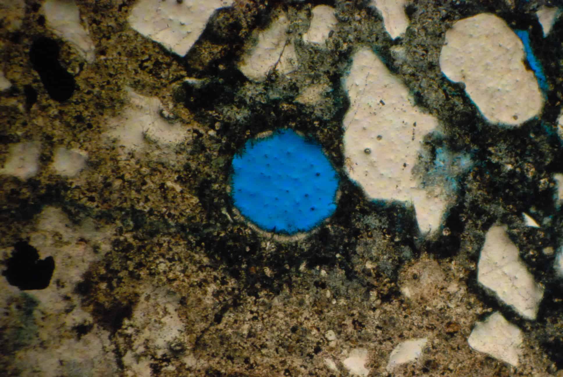
Petrographic analysis involves the optical examination of concrete specimen under low and high power magnification. Detailed instructions on conducting a petrographic examination of hardened concrete/mortar can be found in ASTM C856, “Standard Practice for Petrographic Examination of Hardened Concrete”. For our examination, a representative random sample of concrete near the surface was impregnated with blue dye under vacuum. The impregnation under vacuum causes the dye to permeate every crack, micro crack and all pores, including micro pores in the concrete sample. The impregnated concrete is cut and placed on a glass plate, ground and polished to a thickness of about 30 microns.
The sample was observed by polarizing microscope using a magnification of 40X.
The thin section of concrete was examined for the following features:
- Degree of hydration
- Approximate water-cement ratio
- Composition of fine aggregate
- Air content
- Presence of cracks and micro cracks
- Presence of deleterious reaction products
- Presence of mineral admixtures.
Purpose of Petrographic Examination
The usefulness of petrographic analysis ranges from quality control to predicting future performance of concrete; others include:
- Determination as to whether the concrete/mortar in a construction was or was not as specified.
- Determination as to whether the concrete has been subjected to and affected by sulfate attack, or other chemical attack, or early freezing, or to other harmful effects of freezing and thawing.
- Provide a description of cementitious matrix, including qualitative determination of the kind of hydraulic binder used, evidence of unsoundness of the cement, presence of mineral admixture, the nature of hydration products, adequacy of curing and unusually high water-to-cement ratio of the paste.
- Part of a survey of the safety of a structure for a present or proposed use.
Findings from Petrographic Analysis
Examination of sample revealed the following:
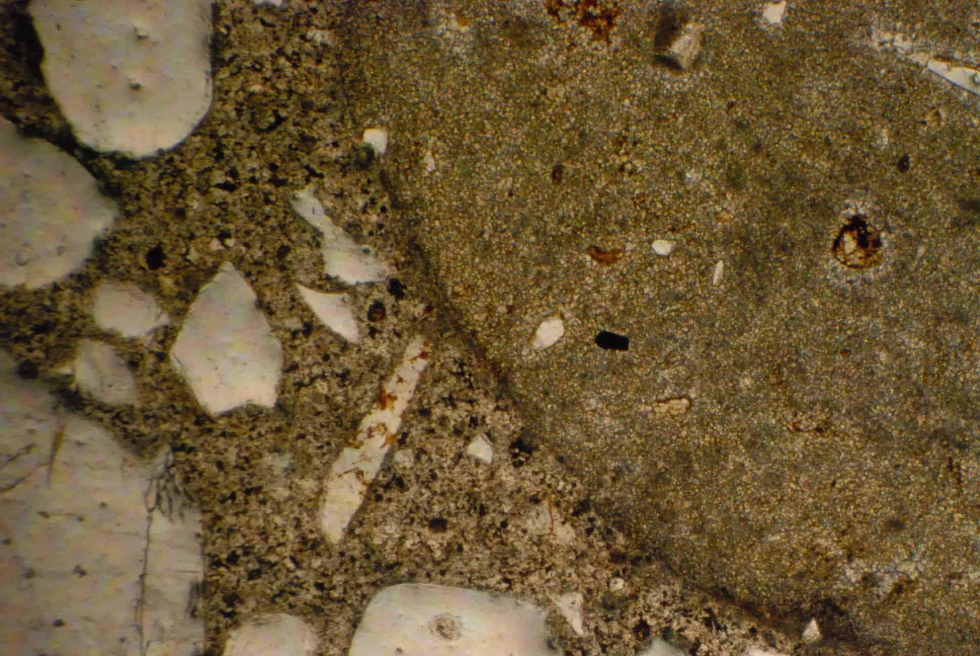
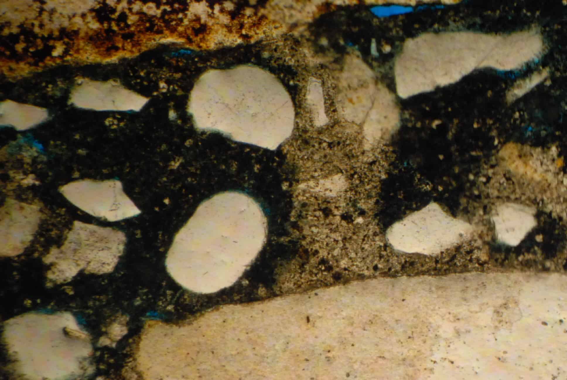
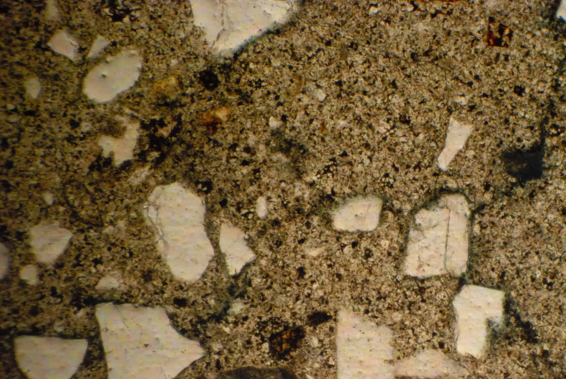
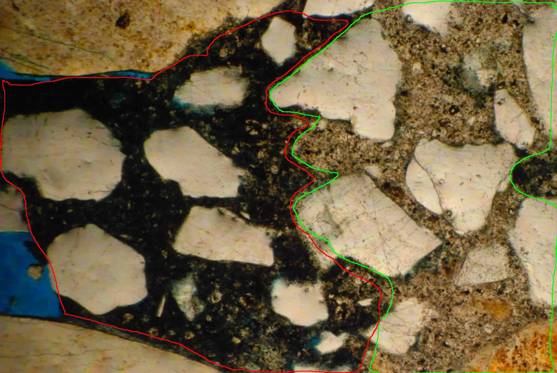
- The concrete was formulated with an estimated cement content of 5 ± ½ sack/yd3 and fly ash content of about 25% by weight of cement. The water to cementitious ratio for the six mixes is in the range of 0.48 ± 0.02. The paste system was differentiated into two areas: predominantly extensive areas of hard set mortar and relatively small patches of normal set mortar.
- Coarse aggregate used was gravel, the fine grained silica type. Fine aggregate used was siliceous sand and appeared to be adequate.
- The concrete was not air entrained.
- The paste appears to be well hydrated and no deleterious reaction product was found in the sample.
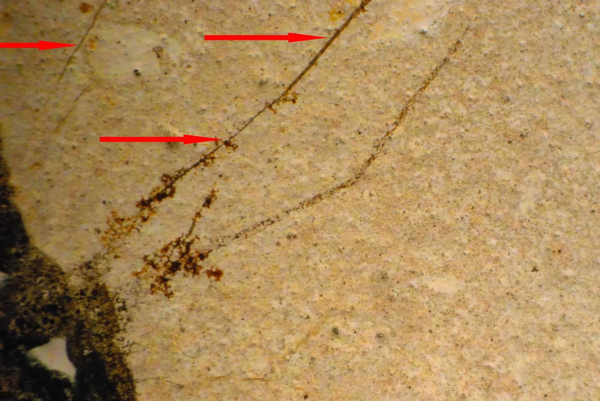
Photomicrographs from the petrographic analysis are shown
DISCUSSION OF RESULTS
The concrete appears to be well formulated with acceptable ingredients of concrete. What stands out in the evaluation is relatively small areas of normal set mortar (blend of cement, fly ash and sand mixed with original water) and areas of hard set mortar. Areas of normal set mortar present relatively low resistance to stresses in the concrete and break initiated at any such area tend to propagate along lines of least resistance. See Figure A-4 in the Appendix.
Several factors can contribute to the differential hardness in concrete. The often cited cause is re-tempering of the concrete. Re-tempering is the addition of water to a hardening concrete and re-mixing it for a while to render the concrete easy to pour and place. Depending on the duration of the mixing, the amount of water added and the degree of hardness attained by the original concrete any number of differential hardness can develop in a particular concrete.
Another probable cause of the differential hardness of the mortar system in concrete is the ineffectiveness of the mixing in the ready mix truck including hardened concrete build-up around the mixing blades.
APPENDIX
Consulting Engineers
Concrete Experts
"C3S, Inc. is a concrete consulting firm dedicated to providing full scale services to civil, A/E firms, government entities, testing laboratories, property managers and owners, and other agencies dealing with projects related to concrete.
With its immense expertise, C3S. Inc. has been successfully serving clients in U.S and worldwide markets for over 30 years. "
CONTACT INFORMATION
C3S, Inc.
7100 Regency Square Blvd.
Suite 183
Houston, TX 77036
Office Hours
Mon-Fri: 8 AM - 5 PM
Sat-Sun: Closed

