Petrographic Analysis & Scanning Electron Microscopy
C3S Petrographic Analysis and Scanning Electron Microscopy Services
Petrographic Analysis and
Scanning Electron Microscopy
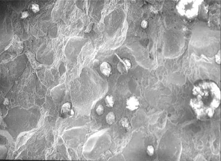
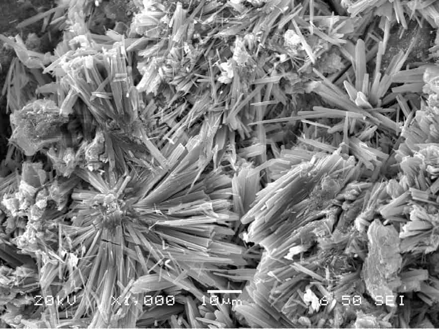
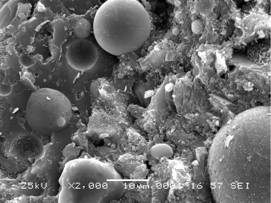
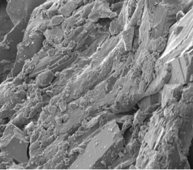
Petrographic analysis involves the optical examination of concrete specimen under low and high power magnification. Scanning electron microscope imaging facilitates identification of hardened cement paste constituents with greater contrast, and greater spatial resolution than for optical methods and provides ancillary capability for element analysis and imaging.
We deliver results based on investigation, testing and analysis. We compile and report all our findings in succinct and comprehensive manner.
Petrographic Analysis
Petrographic analysis is the starting point for evaluating any concrete -from a well-performing concrete or an inferior concrete.
It involves the following steps:
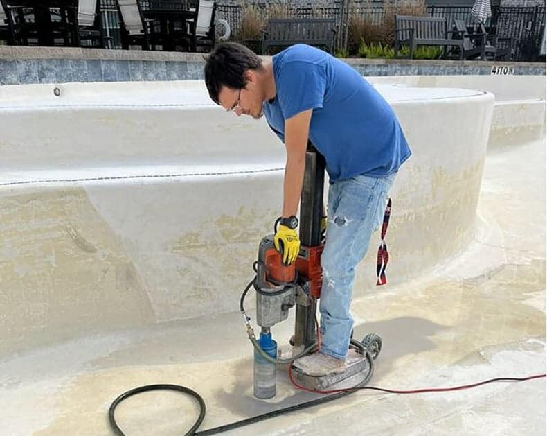
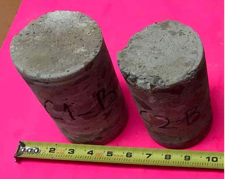
a. The concrete is typically extracted by coring and the cores presented to the laboratory for the evaluation.
b. A standard method of performing the test is by ASTM C856. Other ASTM methods are used in evaluating concrete , its ingredients, and other related materials e.g. masonry.
The purposes of this examination include:
- Determine the cause of a well-performing concrete.
- Determine the causes of inferior quality, distress ,or deterioration of concrete.
- Determine in detail the condition of concrete.
- Determine whether alkali-silica reaction or cement-aggregate reactions or reactions between contaminants and the matrix have taken place, and their effects on the concrete.
- Determine whether the concrete has been subjected to and affected by sulfate attack, or other chemical attack.
- Part of a survey of the safety of a structure for a present or proposed use.
- Determine whether concrete subjected to fire is essentially undamaged or moderately or seriously damaged.
Petrographic Analysis Process
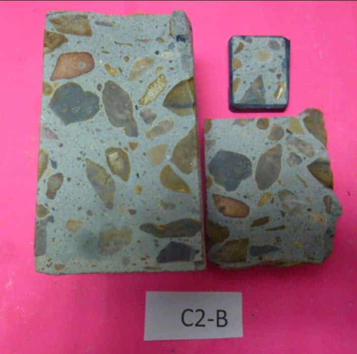
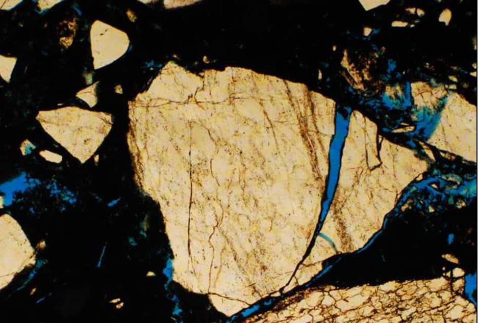
The top 2” x 3” of the smaller part is used in preparing the thin section. The 2” x 3” stub is placed in an oven at about 50ºC to remove moisture from the sawn concrete.
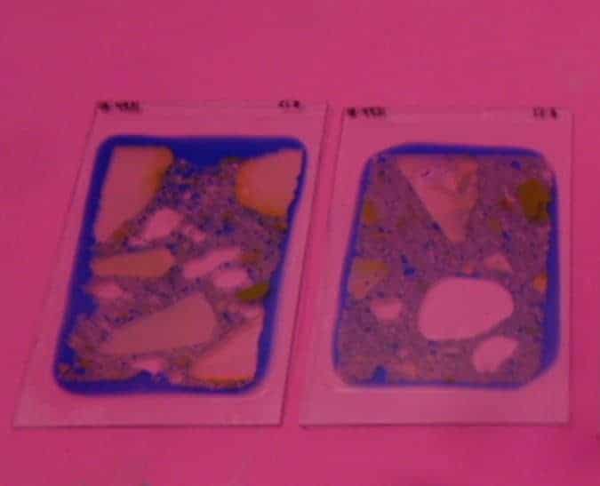
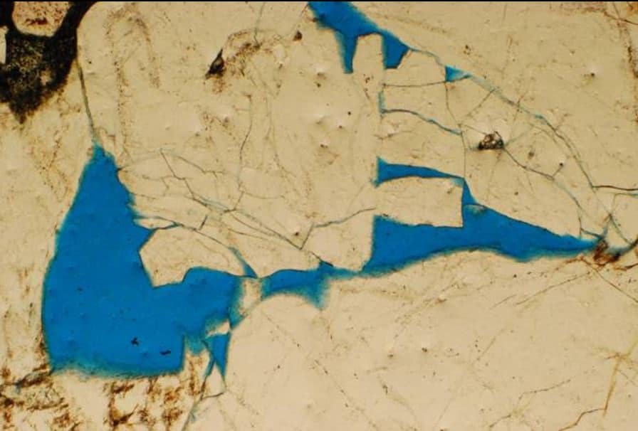
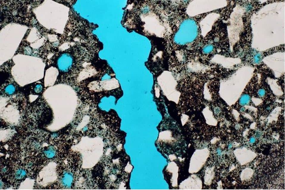
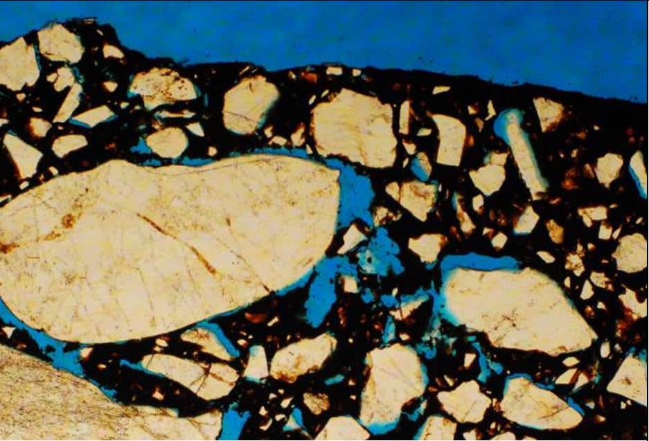
It is then placed in a desiccator with a blue dye and a vacuum applied for the blue dye to permeate every void or crack in the concrete matrix, i.e., the aggregate, hardened cement paste. When removed from this process it is bonded on a glass plate and cut with a fine saw.
The concrete on top of the glass is first ground on a coarse silicon carbide sheet – 100 grit. The process is continued with increasing grinding sheets up to 1,500 grit and to a residual concrete thin section of about 30µm
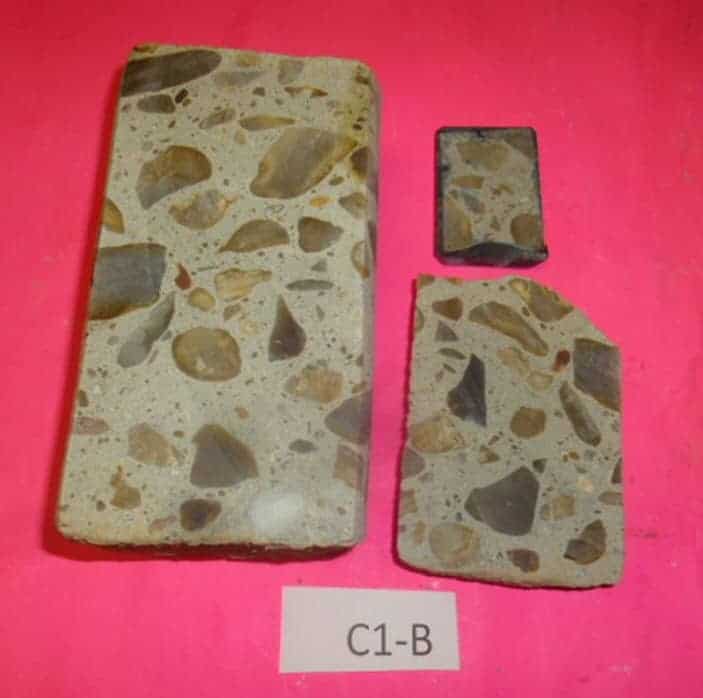
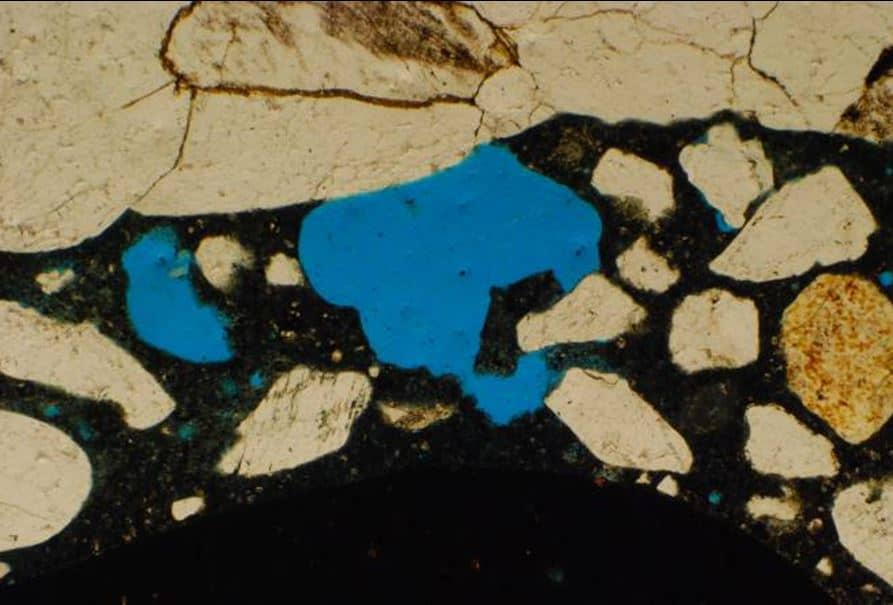
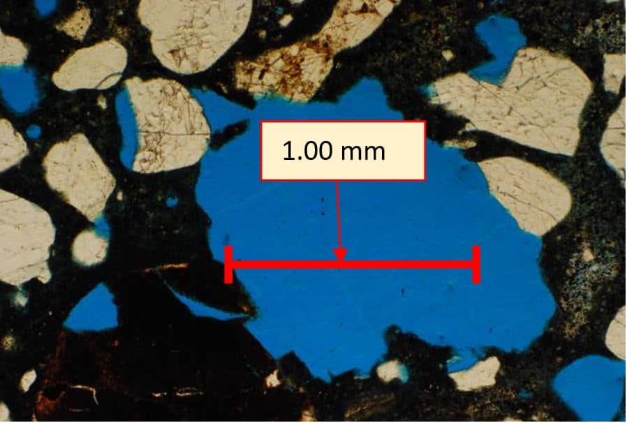
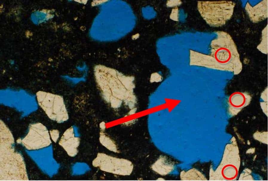
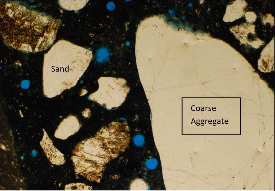
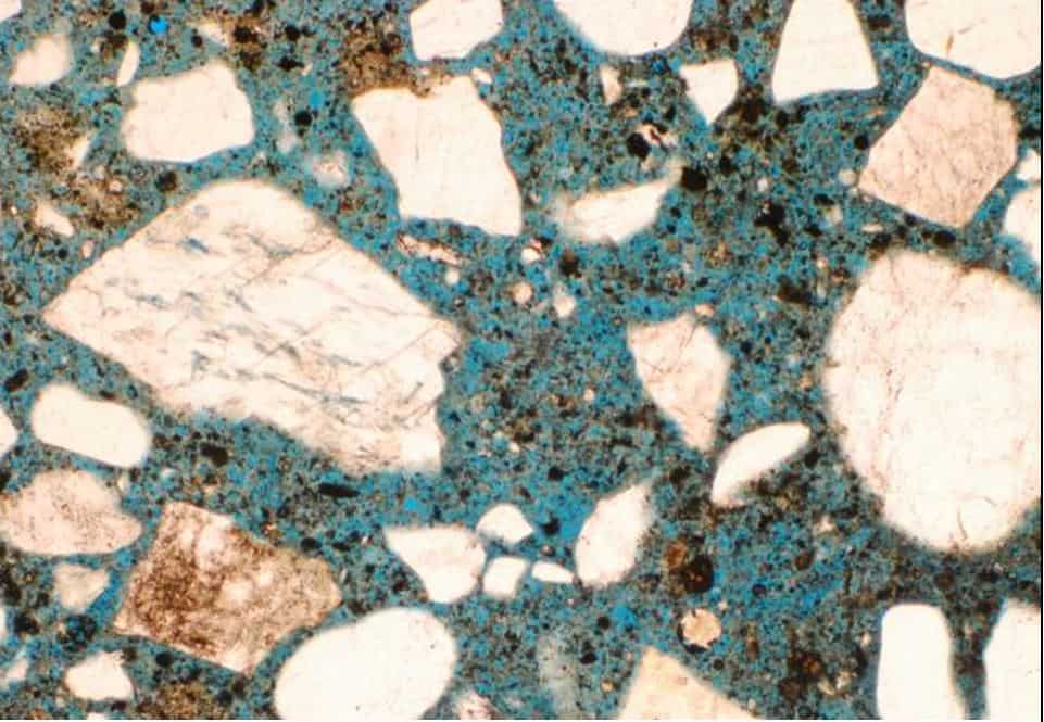
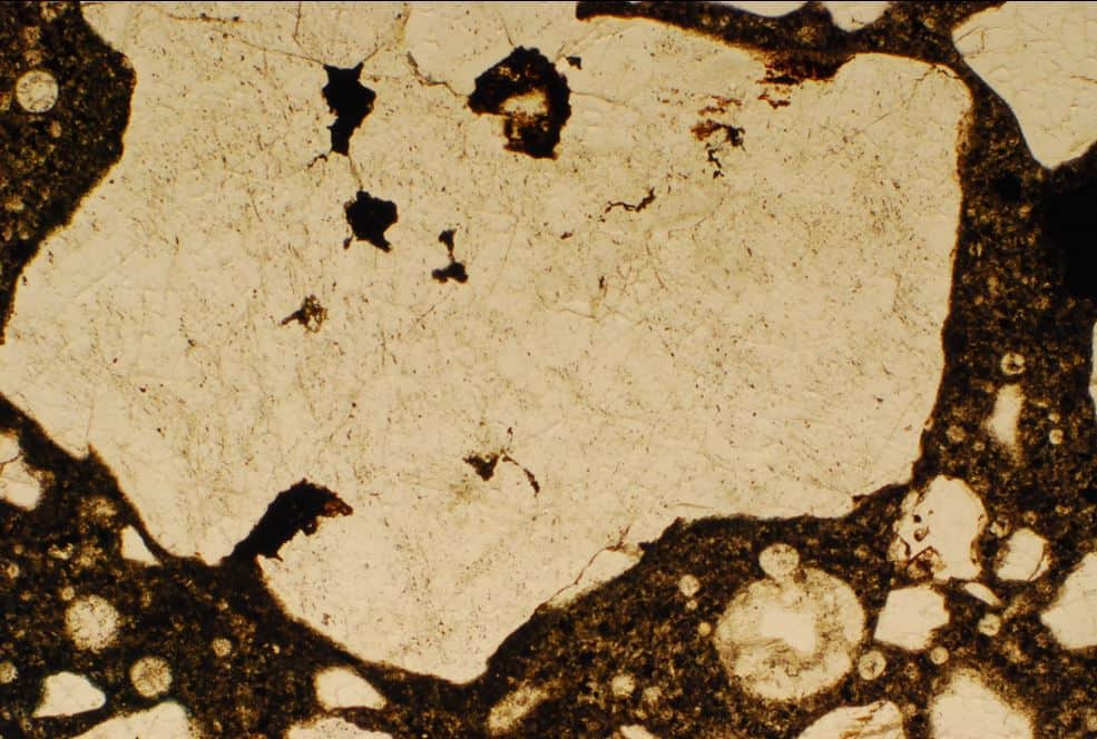
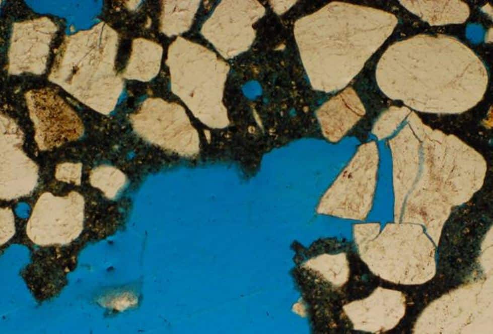
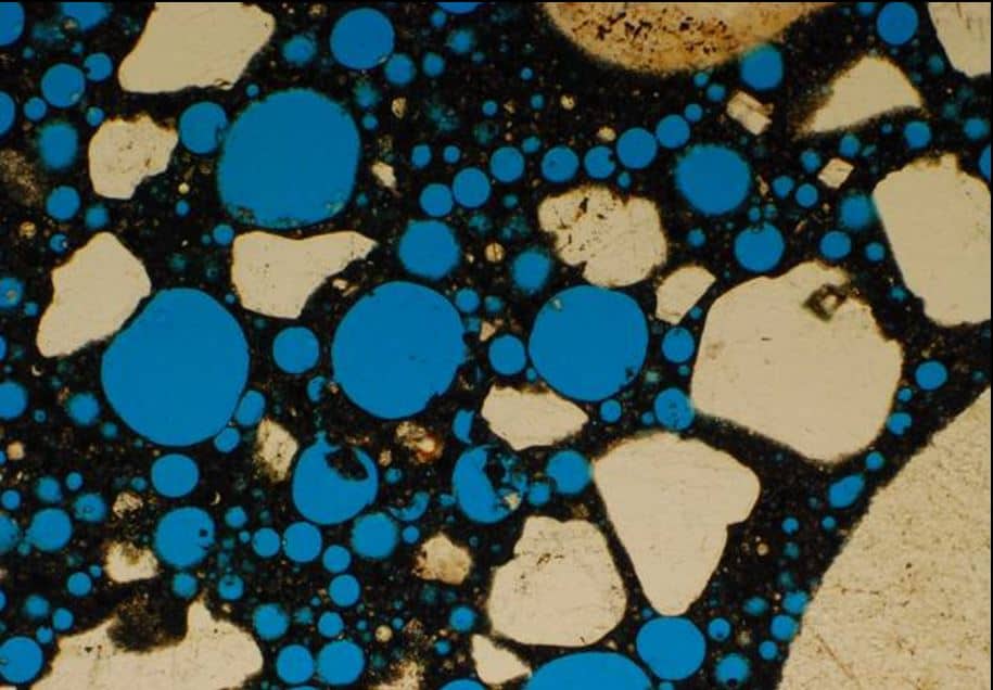
Figure 6 (a to f) shows representative sections of Sample CB-1
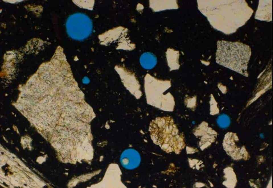
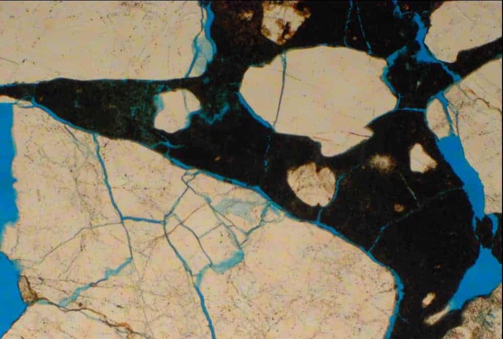
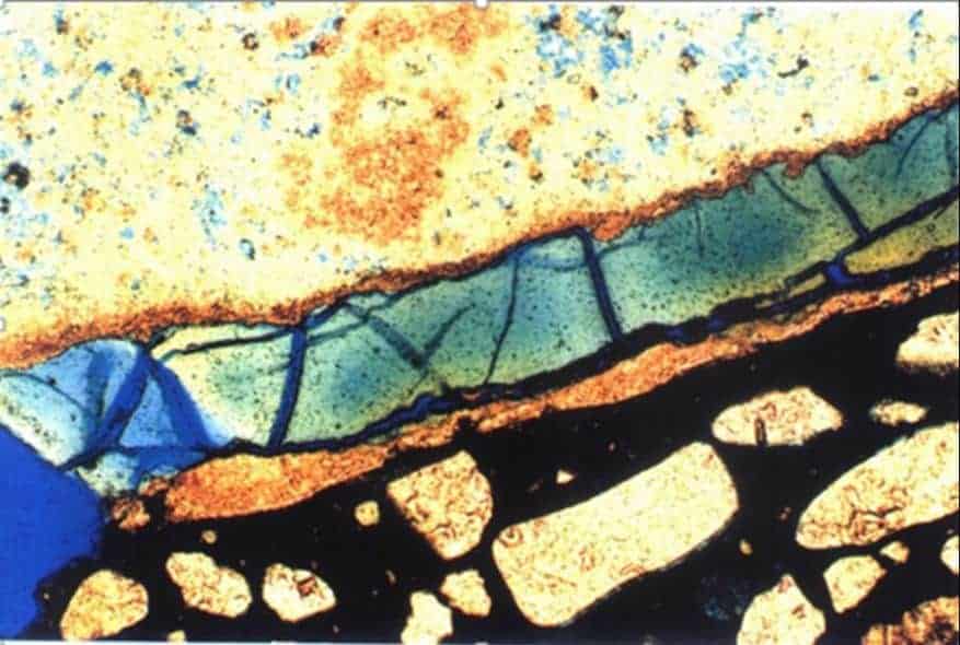
Information gained from petrographic analysis include the following illustrations.
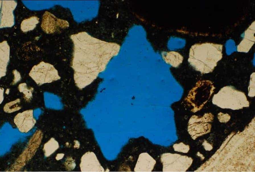
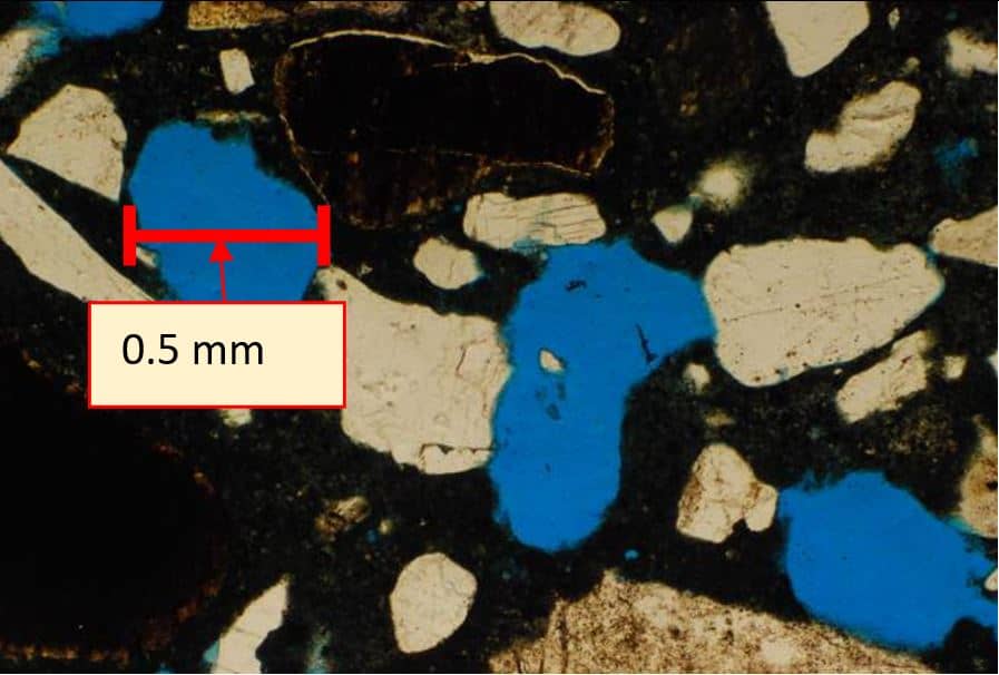
Show a dense uniform cement paste (black background) with the right amount of water content in the mix. The paste holds the coarse aggregate and sand particles. The blue circles are entrained air voids.
Such concretes have high compressive strengths.
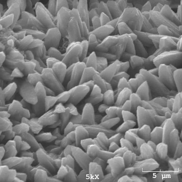
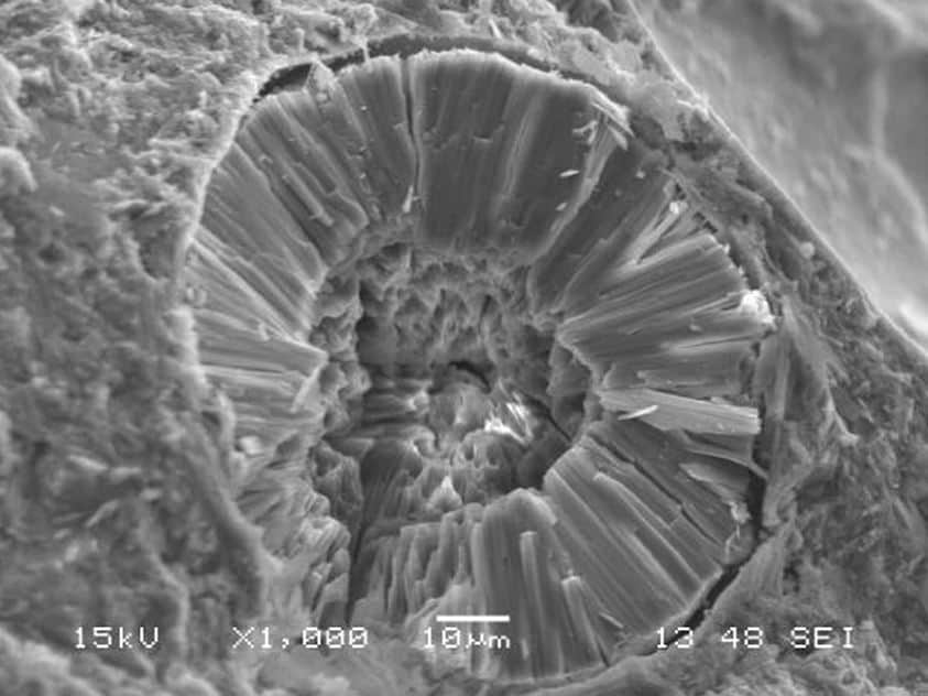
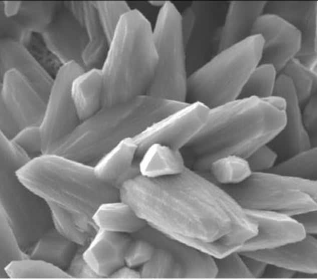
Scanning Electron Microscope Photos
FEATURED PROJECT 1
Problem:
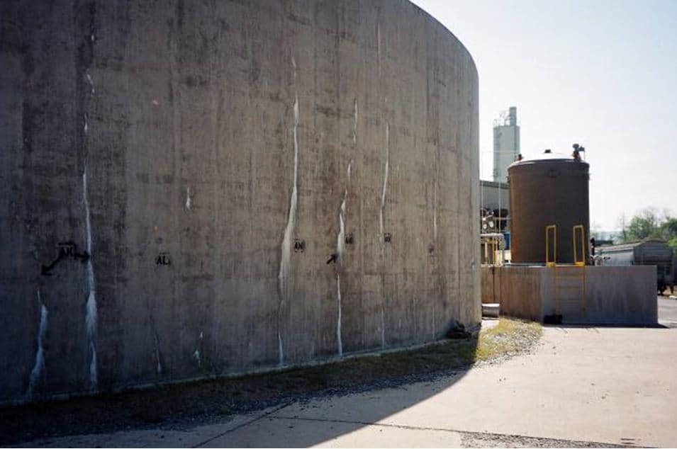
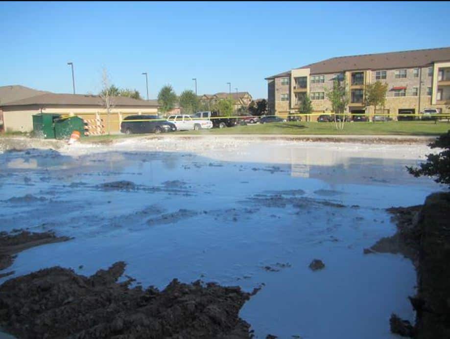
A concrete wastewater tank, less than three years old, had sustained severe cracks around entire tank with efflorescence products oozing from some of the cracks.
Evaluation of Problem:
C3S was contracted to determine probable cause of the problem.
Cores were taken and evaluated by petrographic analysis and scanning electron microscopy.
Petrographic analysis revealed internal cracks, micro porous paste with dense paste patches, indicative of re-tempered concrete, and was air-entrained.
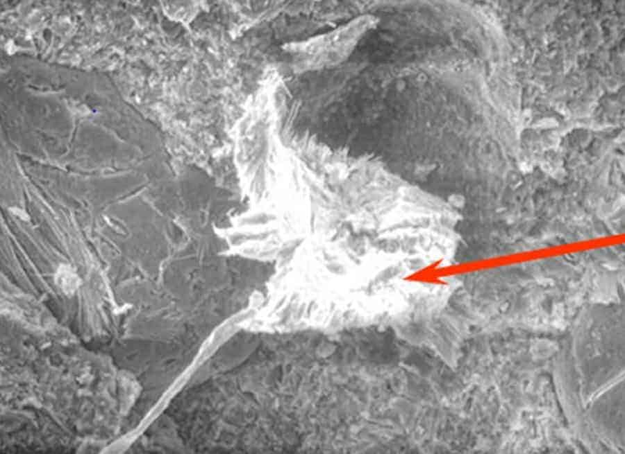
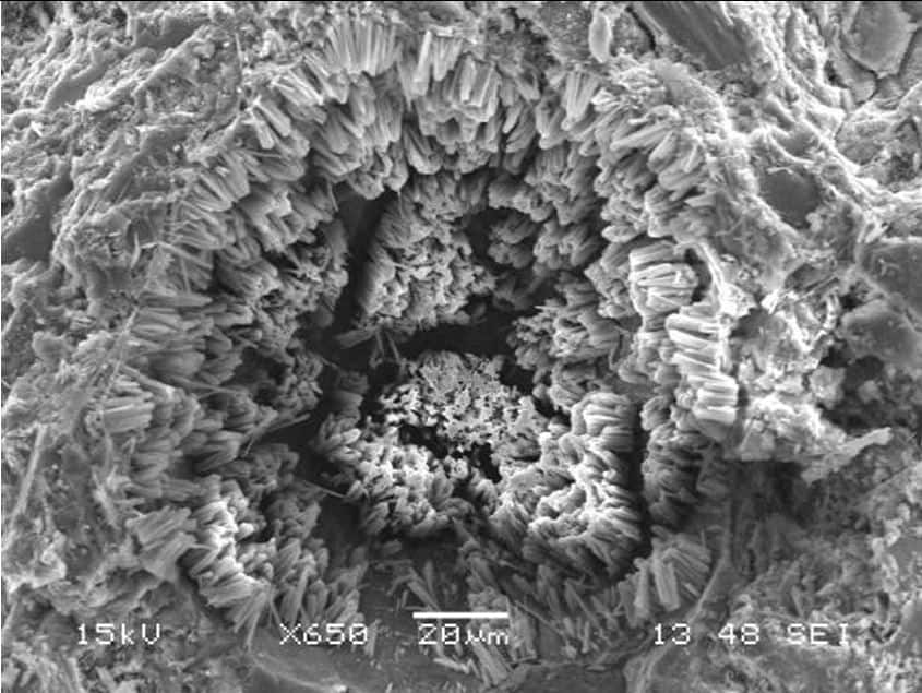
Scanning electron microscopy, SEM revealed copious amounts of ettringite in various stage of formation.
Probable Cause of Problem:
Cement specified for Concrete formulation was Type I/II.
Most often when specifications calls for Type I/II; the preferred cement is Type II.
Type II has lower C3A content (8%); Type I can have as much as 13% C3A content in the cement.
Information on the source of cement was not available. It was also known that Type II cement was not readily available in the vicinity of the plant. Highly probable that the cement used was a Type I with high C3A content which reacted with the high sulfate ions in the waste water to form ettringite. A deleterious hydration product which grows in voids, fill them up and burst out of the voids creating cracks and micro cracks.
FEATURED PROJECT 2
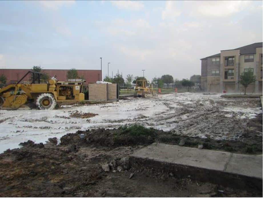
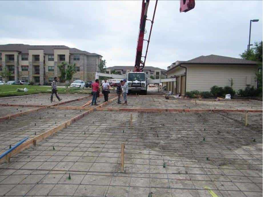
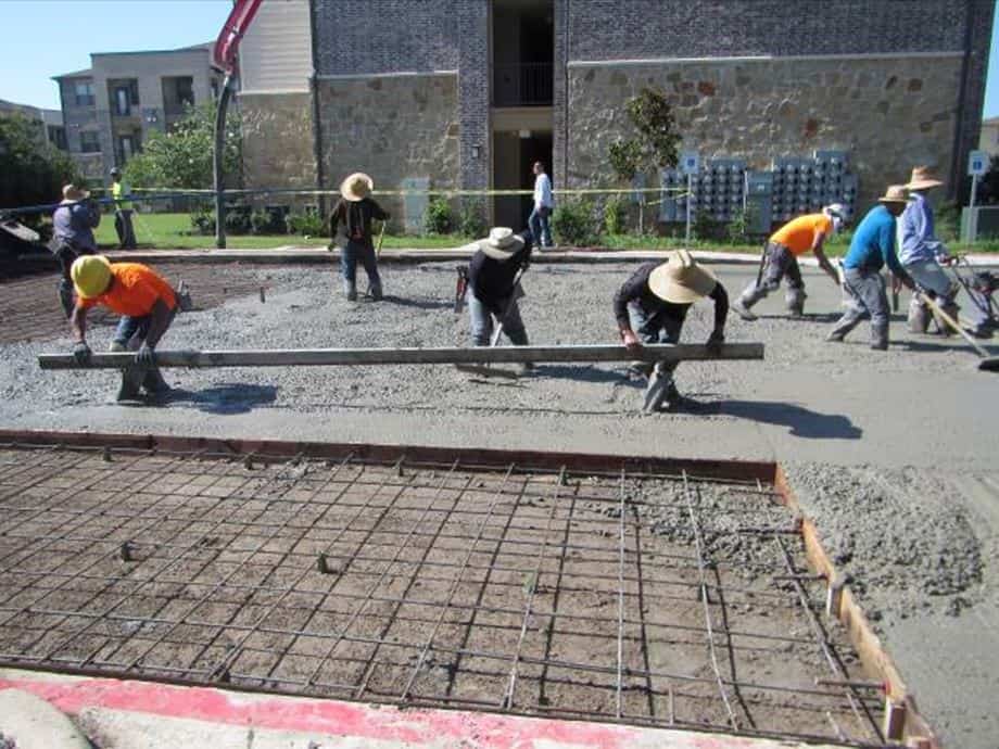
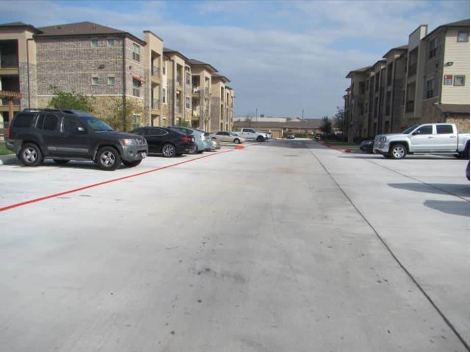
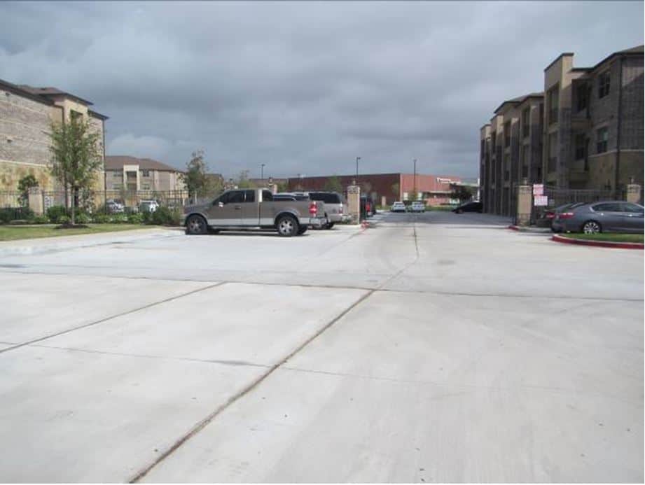
Construction Management – Concrete Driveway Replacement.
Problem:
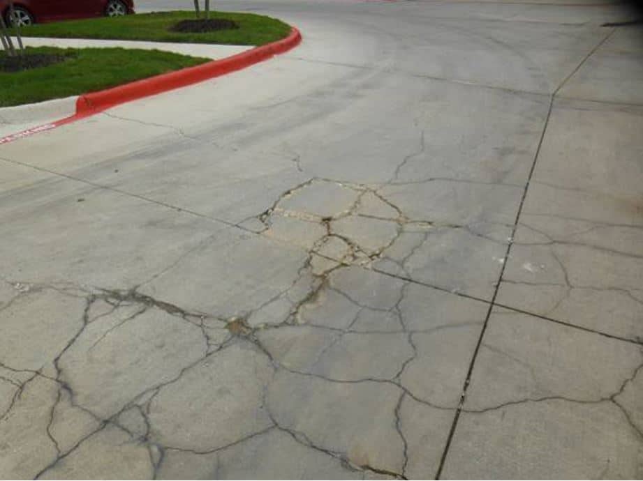
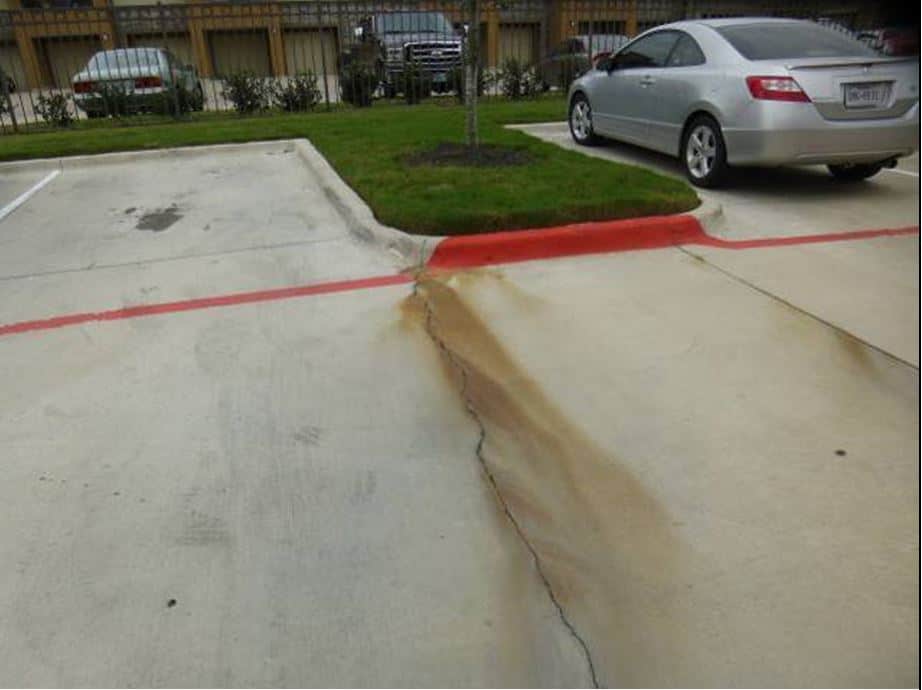
Concrete driveways and parking spaces at a newly built apartment in Houston, less than three years old have sustained serious cracks and other surface defects. Earlier engineering study revealed a fat clay below the slab that was not lime-stabilized.
C3S was contracted to oversee the replacement of the degraded slab with a durable slab.
Solution of Problem:
We obtained resources –
- an independent testing laboratory,
- contractor to break and remove degraded concrete,
- Lime stabilization of clayey soil, and
- Contractor for placement of new concrete
C3S monitored each phase of the project and provided timely report to client.
FEATURED PROJECT 3
Evaluation of Damaged Grout at the base of Coker Units.
Problem:
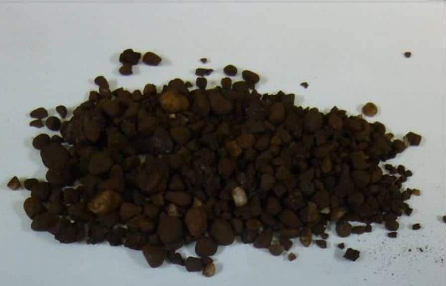
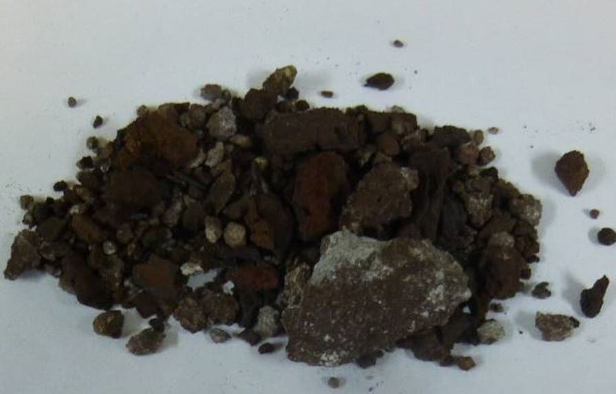
A proposed repair program at a refinery suspected an epoxy grout as the material used at the base of a series of Coker units; the grouts have been damaged. Specification covering the earlier work done was not available. Several samples were taken from a number of the drum units. Two damaged grout samples were submitted to our Consultancy to determine the type of grout material and the probable cause of the damage to the grout.
Finding Solution to Problem:
Two analytical methods were used to evaluate the two damaged samples, they are:
- Petrographic analysis
- Scanning electron microscopy, SEM
Solution to Problem:
With the assistance of two other methods – Thermogravimetric analysis and X-ray diffraction it was concluded that one of the samples was an epoxy grout; the other was a cementitious grout.
One of the significant contributors to the damage was attributed to the aggregates used; it was marginal in quality, with inherent cracks in them.
C3S IS A GLOBAL LEADER IN CONCRETE EVALUATION
We provide quality services that our customers have come to expect.
Consulting Engineers
Concrete Experts
"C3S, Inc. is a concrete consulting firm dedicated to providing full scale services to civil, A/E firms, government entities, testing laboratories, property managers and owners, and other agencies dealing with projects related to concrete.
With its immense expertise, C3S. Inc. has been successfully serving clients in U.S and worldwide markets for over 30 years. "
CONTACT INFORMATION
C3S, Inc.
7100 Regency Square Blvd.
Suite 183
Houston, TX 77036
Office Hours
Mon-Fri: 8 AM - 5 PM
Sat-Sun: Closed

